Fixing damaged PCB for keyboard switch on a Keyboardio
Posted on
I've owned a Keyboardio Model 01 keyboard for some time now (nearing 10 years since I backed the Kickstarter apparently), during that time the switches have broken on a few occasions. The first time a switch broke I ordered a set of 10 new switches so that I had a stash for future breakage. Replacing the switch was pretty easy, you unscrewed a few screws to access the switches and PCB. Using your soldering iron you'd remove the solder holding the broken switch, stick a new switch in there and add some new solder. Good as new!
The other month one of my keys started acting weirdly and it was once again time to change a switch. Unfortunately for me, this time, I was a tad bit impatient while removing the switch.. It ended with me breaking part of the trace on the PCB for the switch I was removing, and once the new switch was in place that key no longer worked. Initially this seemed like it would be hard to fix since I don't really know of any obvious ways to "redraw" traces on a PCB. Along with this, the side from which the switch attached had little to no access to the PCB due to a metal plate which gave the switches a bit of distance to the PCB along with holding them in place.
After some thinking I realized that the other side of the PCB had some probe points which were probably used during production to check all connections. My idea was to use these points as soldering points to add some new wires, hopefully bringing back the correct connections to allow the PCB (and keyboard) to work again. The only problem with this is that this other side of the PCB is pretty close to the inner part of the enclosure around the PCB and keyboard plate, so space is limited. Regardless, it was worth a try as I didn't want to give up on the keyboard due to user error :)
To know which probes to connect I needed to figure out how the pads were supposed to be connected, had I not broken a few traces. I probably could have figured this out by measuring known working switches and their relations to each other with a voltmeter. However, the keyboard is supposed to be hackable and there are some schematics that you can check: left hand schematics, and some kind of pcb layout. I'm not quite sure the PCB layout is the one used for Keyboardio model 01, but it gives pretty much the same idea and I believe the key matrix is the same for the purposes of fixing a trace in the PCB.
Armed with the above two documents I was able to figure out which points that needed to be attached
to each other for the switch to have a chance to work again. Looking at the left hand schematics
I realized that in my case I needed to reconnect (row2, col0) with (row2, col1) and (row2, col1)
with (row2, col2) (see page 3 of the left hand schematics). Along with this
I also needed to insert a new diode since I had crippled the connection to the built in one when
yanking out the old switch. I used what I had available which was a waay bigger one than necessary
and I connected it from col3 to the the same side of the switch as for a working switch. To figure
out which side was the correct one I used the diode mode on a voltmeter, this also showed me which
way to turn the diode. Doing it that way meant I didn't have to fully understand the schematic and/
or layout I had found.
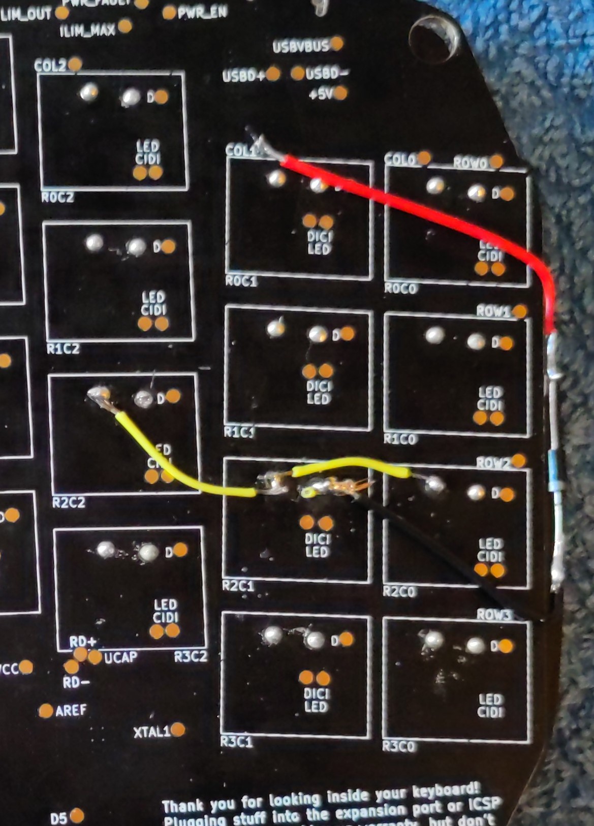
Once all that was done and the switch was soldered in place the key worked! Here's a picture of what I did, notice that I put the diode on the side since I wasn't sure it would fit in the enclosure otherwise. The yellow cables are the interconnection between columns on the same row while the black and red cables are for the diode.